Last updated: October 18th, 2023
A garage door is the finishing touch that can elevate the overall look of your home to a trendy and modern level. Nevertheless, garage doors are complex pieces of equipment, and their installation must adhere to manufacturer recommendations and industry standards to ensure proper functionality.
This detailed post provides instructions on framing a garage opening and installing a garage door. These methods and techniques can be implemented when you’re installing or even repairing your own garage door.
How to Install a Garage Door – Where to Start
Before purchasing and installing a garage door, it’s essential to measure the garage door opening to determine the appropriate door size. As a rule of thumb, the garage door dimensions should match the frame dimensions.
Additionally, ensure that the garage frame and header are in good condition and properly proportioned to facilitate the safe installation of hardware and supporting brackets.
You also need to confirm that the clearance between the garage opening and the ceiling allows for the smooth installation of the torsion system.
The tools required for the job:
- Impact driver.
- 5/16-inch impact socket.
- 3/18-inch impact socket.
- Impact socket extension bar.
- 2 vise grips.
- 2 winding bars.
- 7/16 inch (11mm) 12 points wrench.
Framing Your Garage Opening
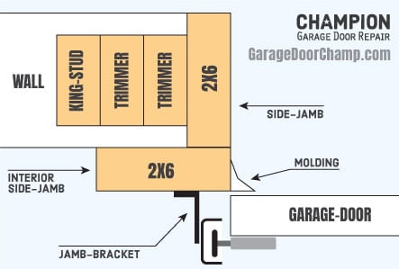
Both side jambs of the garage door opening should be flush with the interior wall or studs. To properly mount the garage door tracks, you’ll want to have a clearance of at least 3-4 inches past the opening.
Both side jambs of the garage door opening should be flush with the interior wall or studs. To properly mount the garage door tracks, you’ll want to have a clearance of at least 3-4 inches past the opening.
If you use extra studs on the interior to align the wall with the garage frame, ensure that these studs are long enough for secure attachment to both the top (or header) and sole plates. Incorrectly installed studs may detach from the wall over time.
Header and Headroom
The ideal header height, measured from the garage opening to the ceiling, is 9 inches or more. However, it can be reduced to 5 inches. In such cases, a low clearance kit must be installed.
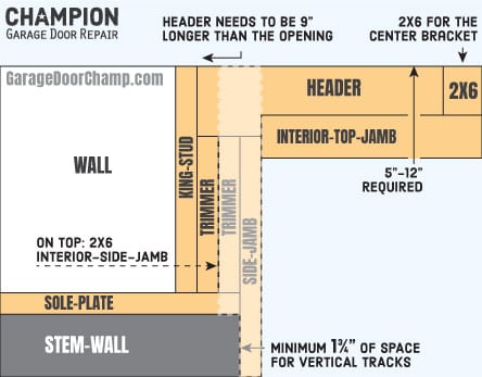
The minimum clearance required is 3-4 inches. In such cases, the torsion system will be installed at the back rather than on the garage’s header. It’s important to note that the header should be flush with the wall or side studs. This ensures proper alignment of the torsion system’s center bracket with the end plates.
Keep in mind that the center bracket experiences constant pressure due to the torque generated by the torsion springs. Therefore, it must be securely fastened to the header.
Vertical and Horizontal Tracks
The garage door vertical tracks and jamb brackets, together, require 3-4 inches of side clearance measured from the opening. Ensure that the concrete stem-wall does not obstruct this clearance. The vertical tracks need a minimum of 1 ¾ inches of clearance from the opening to the stem-wall. If there is insufficient clearance, you will need to cut the concrete.
The horizontal tracks require adequate backroom space, calculated as follows: (Garage Door Height) + (16 Inches) = Required Backroom. In instances where a support beam is located in the middle of the garage, you may consider using a low headroom kit or cutting the tracks to fit. However, please be aware that cutting the horizontal tracks may result in the garage door not fully opening.
The Garage Door
As mentioned before, the garage door dimensions should match the garage opening. For example, if the garage door opening is 16 feet wide by 7 feet high, then the garage door should also be 16 feet wide by 7 feet high.
Identifying the Garage Door Sections
Once the garage door opening is prepared for installation, and you have a garage door on hand, your first step is to identify the garage door’s bottom panel, the intermittent panels, and the top panel.
Hinges and Brackets
The hinges connect the garage door sections and should be correctly matched to each section. Additionally, the hinges function to gradually pull the garage door sections away from the wall to prevent binding. Intermittent hinges should always be hinges #1, regardless of the specific panel. However, the end hinges should be chosen to suit the particular section.
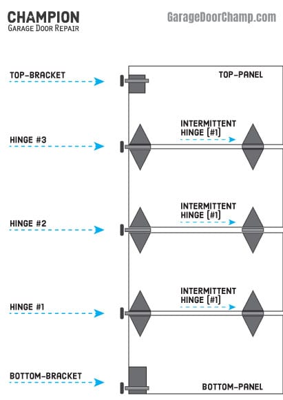
For instance, the very bottom section should be connected to the 2nd section using #1 hinges at its ends. Likewise, the 2nd section should connect to the 3rd section with #2 hinges at its ends, and so forth. Ensure that the top brackets for the top section are securely screwed in and adjusted in accordance with the manufacturer’s specifications.
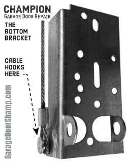
Here’s a rule of thumb: when adjusting the top brackets, they should not apply excessive pressure to the top section against the wall, but they should also prevent gaps. For the very bottom section, mount two bottom brackets on both the left and right bottom corners of the section. You can typically use 5/16” x 1″ Hex Washer Head Self-Tapping Screws for this purpose.
Installing the Garage Door Sections: Two Methods for Stacking
There are two methods for securing the garage door sections while stacking them. The first approach is to install the vertical tracks first, using the rollers to hold the sections in place. The second method is to use temporary 3-inch nails and slightly bend them over toward the sections.
Begin with the very bottom section. Mount the bottom brackets, end hinges, and intermittent hinges in their respective positions. Place the bottom section at the center of the garage opening.
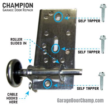
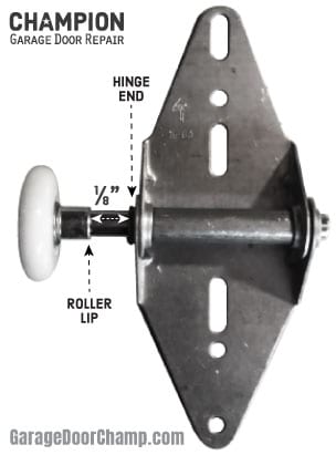
Before stacking an additional section, slide the rollers onto the hinge’s shaft (note that the roller always slides into the hinge’s bottom shaft) and ensure the roller’s wheel is securely positioned inside the track. Then, connect the sections using the hinges.
Throughout the process, make sure the sections are consistently centered within the garage opening and flush at the ends.
Vertical Tracks
To adjust the jamb brackets, begin by loosely mounting them on the track at the designated area. When positioning the vertical track, ensure that the flat side faces the wall, while the slightly curved side faces towards you.

When the vertical track is roughly positioned in place, use lag screws to secure the jamb brackets to the wall or studs. Typically, we use Zinc Hex Lag Screws sized 5/16″ x 2″ for this purpose.
You might consider drilling the screws in the center of the jamb bracket area for ease of adjustment. During the installation of the vertical tracks, ensure that they do not exert excessive pressure on the rollers against the hinge. Achieve this by positioning the vertical tracks slightly farther away from the door, creating an approximate 1/8” gap between the hinge and the roller’s lip.
Flag Brackets and Horizontal Tracks
With the vertical tracks positioned and mounted in place, the flag brackets should be attached to them. The flag bracket should be properly leveled and mounted with lag bolts to wall using Zinc Hex Lag Screw 5/16″ X 2″. Once the flag bracket is in place, you can proceed to the horizontal tracks. An easier way to adjust and align the horizontal tracks is to loosely and temporary held by a rope hanging from the rafters.
You can loosely attach the horizontal tracks to the bottom area of the flag bracket and loosely attach them with a solid punched angle to the middle/upper section of the flag bracket. Most horizontal tracks already have built-in angle that can be mounted to the flag bracket.
Alignment of the Tracks
If you’ve used temporary nails to secure the door sections in place, it’s now time to remove them. To prevent any binding, avoid positioning the tracks too closely to the wall, as this can exert excessive pressure on the garage door sections. If there’s a small gap left, it can be covered later with an exterior vinyl molding.
Start at the bottom jamb bracket of the vertical track and work your way up to the others to ensure that the door is not pressed too tightly against the wall. Adjust the distance as needed.
Once the vertical tracks are properly adjusted and positioned, it’s time to level and secure the horizontal track to the rafters using sturdy pieces of punched angle. Typically, we use 16-gauge punched angle and 5/16″ x 2″ Zinc Hex Lag Screws for this purpose.
At this point, all bolts should be tightened on both the left and right tracks (horizontal and vertical), ensuring they are adjusted, leveled, and positioned correctly.
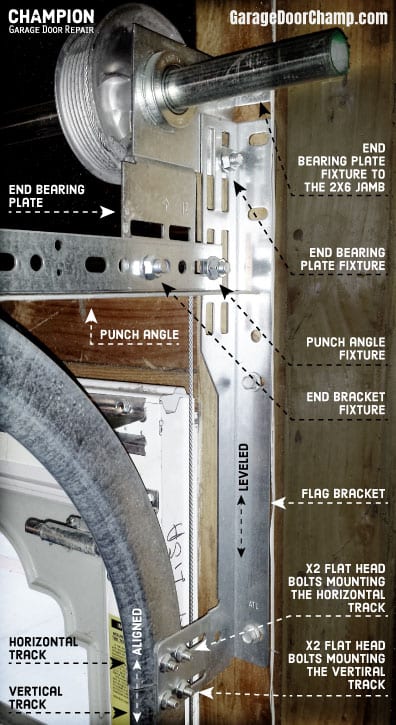
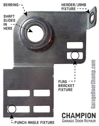
End Bearing Plates
There are two types of end bearing plates: supported and unsupported. The supported end bearing plate is primarily used for standard overhead door systems, where we have at least 12 inches of clearance between the garage opening and the ceiling.
The supported end bearing plates are mounted to the flag bracket, the punched angle of the horizontal tracks, and the header.
The unsupported end bearing plate is primarily used for low headroom overhead door systems, where there is less than 12 inches of clearance between the garage opening and the ceiling.
The unsupported end bearing plates are mounted to either the flag bracket or the punched angle of the horizontal tracks, and in some cases, to the header.
Both end bearing plates must be leveled with each other and secured with 3/8″ Flat Head Screws to the flag brackets, the punched angle of the horizontal tracks (ensuring the flat side of the screw faces the garage door), and to the header using 5/16″ x 2″ Zinc Hex Lag Screws.
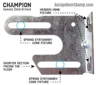
Center Bracket
The center bracket serves the dual purpose of securing the torsion springs in place and providing support for the torsion tube. There are two types of center brackets: the slotted spring anchor bracket, which does not include a bearing, and the spring anchor bracket with a fixed bearing.
In both cases, the center bracket must be aligned and leveled with the end brackets to establish a centerline. To secure the center bracket correctly to the header, use either 5/16″ x 3″ Zinc Hex Lag screws or 3/8″ x 3″ Zinc Hex Lag screws.
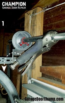
Torsion Tube
After correctly positioning and installing the end brackets and center bracket, you can slide the torsion tube (essentially an axle) through them. If the torsion tube is not level, the center bracket and end plates must be properly adjusted and aligned.
A misaligned garage door torsion assembly can lead to shaft grinding, improper operation, and breakdowns.
Torsion Springs
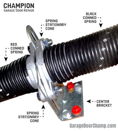
The garage door torsion spring consists of a stationary cone and a winding cone. The stationary cone secures the spring to the center bracket, which is also known as the spring anchor bracket. The winding cone is used to wind up the spring and mount it onto the torsion tube once it’s correctly deflected.
The number of required springs depends on the weight of the garage door and can range from a single spring to four springs. It is advisable to install at least two springs on your garage door.
The springs must be installed on the correct side of the center bracket. Typically, the red cone spring (RW) is installed on the left-hand side (when facing the garage door from inside), and the black cone spring (LW) is installed on the right-hand side. Both springs should be positioned with the coil ends facing upward, toward the ceiling.
If the manufacturer provides a slotted center bracket, a center bearing should also be included and positioned inside one of the springs’ stationary cones before installing the spring.
With the torsion tube in place, alternately pull it out and slide the springs onto it from the loose end to the desired position. Once the springs are properly positioned, securely fasten their stationary cones to the center bracket using a 3/8-16 x 1 1/2″ Hex Head Bolt and a 3/8-16 Flanged Hex Nut.
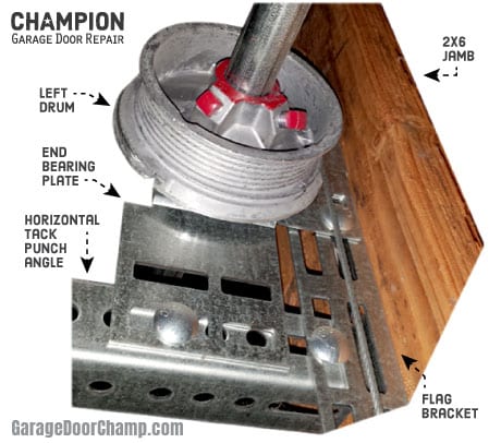
Lift Cable Drums (Pulleys)
Lift Cable Drums (or pulleys) are used to connect the torsion tube to the garage door bottom brackets through the cables, rotating around the x-axis. Due to the shape of the drums’ grooves, it’s essential to install them on the correct side, with the set of locking bolts facing towards the spring anchor bracket.
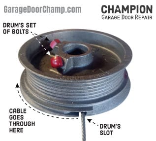
The red drum, labeled ‘L’, should be positioned on the left-hand side, while the black drum, labeled ‘R’, should be positioned on the right-hand side. As you alternately pull the tube out, you can position the drums in their respective places.
Cables
The garage door cables are the sole components that connect the garage door to the torsion assembly. For a standard residential garage door, the cable length should be calculated as follows: Garage Door Height + 18 inches = Cable Length.
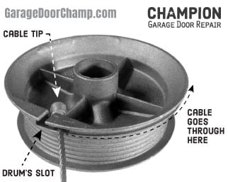
The cable attaches to the bottom bracket using a loop, passes behind the rollers, and connects with a tip to a designated slot on the drum. Most standard residential garage doors use 1/8″ diameter cables, while custom wood garage doors may require 5/32″ diameter cables.
Before proceeding, it’s important to ensure that the following conditions exist:
- The cables are securely hooked onto the bottom bracket’s lip and positioned correctly behind the rollers.
- The cables pass behind the torsion tube and are properly secured in the drum’s slot.
- The torsion tube is adequately extended beyond the ends of the end bearing plates on both sides.
Winding Up the Springs and Balancing the Garage Door
Starting at the left-hand side drum, wrapping the cable is easily accomplished by positioning it in the drum’s groove and rotating the drum toward the ground (counterclockwise). During this process, it’s important to ensure that the cable remains within the groove.
Before tightening the drum’s locking bolts, it’s important to check for any gaps between the end bearing plate and the drum. You can easily do this by pushing the drum towards the end bearing plate.
After properly wrapping the cable around the pulley, use your left hand to keep the cable taut by rotating the drum counterclockwise and holding it in place. While the cable is tight, use a 7/16-inch (11mm) 12-point wrench with your right hand to tighten the drum’s locking bolts securely in place.
Securing Bolts Right
Door manufacturers provide specific torque values for the drum and spring’s locking bolts. However, even experienced technicians often tend to over-torque or tighten these bolts excessively. Over-tightening the locking bolts can easily lead to damage and deformation of the torsion tube.
Equipment manuals and product information typically do not include the required torque values for the drum and spring’s locking bolts. However, in most cases, the manufacturer’s recommendations are as follows: once the bolt has made contact with the tube, an additional full revolution is needed.
Leveling the Garage Door
It’s crucial to balance the tension in both cables before winding up any springs. Ensure that the left-hand drum and cable are under constant pressure before proceeding to the right-hand drum.
You can achieve this by using 2 locking vise grips: first, clamp one locking vise grip onto the tube and gently pull it downward and toward the ground (counterclockwise). While maintaining this pressure, clamp the second vise grip onto the tube, positioning it against the header.
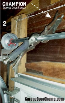
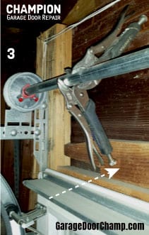
Note that when you pull the first locking vise grip set, applying a moderate amount of pressure is more than sufficient. Remember that the right-hand drum and cable are being tensioned manually, without the use of any tools.
After securing the second vise grip against the header, clamp the first locking vise grip onto the tube, pulling it down against the door’s top section or header.
Securing a vise grip against the door’s top section or header is a safety precaution. The vise grip will keep the garage door in the closed position in the event that an excessive amount of torque is applied to the springs or if the wrong springs are provided.
As you move to the right-hand drum, it’s essential to double-check that the cable tip is properly placed in the drum’s slot. Using the right-hand side, rotate the drum downward against the ground (clockwise), simultaneously wrapping the cable in the drum’s groove. Once that is done, use a 7/16-inch (11mm) 12-point wrench with your left hand to tighten the drum’s locking bolts, all while maintaining pressure on the drum.
After tightening the drums on both ends, it’s important to ensure that both cables have approximately the same amount of tension. You can make a rough assessment of the tension levels by tapping the cables with your finger. You can also compare how level the top panel is with the header and ceiling.
If one cable has significantly more tension than the other, or if the door is not level, it’s advisable to readjust the drums to create similar tension levels for both cables.
Winding Up the Springs
This step can be highly dangerous due to the springs’ high torque. It’s essential to take proper safety precautions, including using designated winding bars instead of thin pieces of metal like screwdrivers. Ensure that the winding bars you use fit properly into the designated slots of the spring’s winding cone and can withstand the stress.
If designated winding bars are not available, you can use 16 to 18 inches long #10 M Rebar and slightly grind the ends to make them fit into the winding cone’s slots.
Door manufacturers have a precise set of torque values for their garage door springs. These values are calculated based on factors such as the weight of the garage door in relation to the door’s height, travel distance, and the horizontal tracks’ radius.
Rule of thumb: the number of turns applied to the spring when it’s wound up should be equal to or slightly exceed the garage door’s height. For instance, if the garage door is 7 feet tall, the spring should be turned 7 full turns or more.
Before winding up the spring, it’s a good idea to take a reference point of where the locking bolts on the winding cone are while the spring is resting on the tube. This way, you’ll be able to determine what a full turn is. Ensure that the locking bolts on the winding cone are fairly loose and not binding against or grinding the tube when the spring’s cone is rotating.
The Springs Winding Process
Starting with the left side (red cone spring), keep your body and limbs as far away as possible and have a 7/16-inch (11mm) 12-point wrench within reach. Begin at the first winding cone, inserting the winding bar all the way into the slot. Once it’s properly inserted, push the bar upward toward the ceiling (in the direction of the coil). When you have clear access to the next slot, insert the second winding bar all the way into the winding cone’s slot and push it upward toward the ceiling.
Continue turning the spring until you achieve the required number of turns. If you miscount, unwind the spring and start over from the beginning.
After reaching the required number of turns, use a 7/16-inch wrench to tighten the locking bolts on the winding cone. Once the red coned spring is wound up and mounted to the tube, proceed to the black cone spring.
Note: the spring will become longer as it is wound. In a standard residential setting, by the end of the winding process, the spring should be approximately 2 inches longer than its original length.
Testing the Garage Door
Before removing the vise grip, ensure that all the fixture nails are pulled out (if used when stacking up the sections), all bolts and screws are tightly secured, the tracks are correctly mounted and leveled in place, and that there is nothing obstructing the garage door’s path.
Begin with the lower locking vise grip that is secured to the door’s top panel or header: firmly hold the upper locking vise grip, which is fastened to the header, and release the lower locking vise grip set.
Slowly and cautiously turn the upper locking vise grip set toward the ground (counterclockwise), ensuring that the garage door does not lift forcefully.
If the garage door is pulling up hard, push the locking vise grip back against the header and hold it in place. Then, reattach the locking vise grip that you removed to the door’s top section or header. Unwind the springs and restart the winding procedure from step one, ensuring that you apply the correct number of turns.
If the garage door is too heavy, reattach the vise grip that you removed to the door’s top section or header. There are two ways to address this. The first is to add turns to the springs until the garage door is properly balanced. The second method is to completely unwind the springs and restart the entire process.
Learn how to properly check the garage door balance.
Molding and Weather-stripping
Garage door weather-stripping serves to prevent water, dust, and critters from entering your garage. It’s used to seal any gaps between the garage frame and the garage door. Start by measuring the garage opening and cutting the molding to the same size. When installing the molding strips, press them against the door and secure them to the frame using a nail gun.


I want to make sure that I get my garage door installed properly. I didn’t even think about the measurements that I need to keep in mind with my garage door! It would be a good idea to get a professional to take a look at this, since they know how to gather those kinds of measurements.